Posts Tagged diffuser panel
You say “Diffuser,” I say “Diffusor”
Posted by Acoustics First in Diffusion, Q&A, Uncategorized on November 11, 2025
If you’ve spent any time around acoustic treatment—especially sound diffusion—you’ve probably noticed something odd: sometimes the product is called a “diffuser“, and other times it’s a “diffusor“. For newcomers, this can feel like a secret code or a subtle technical distinction – But the truth is much simpler.

Many trace the dual spelling back to Manfred Schroeder, the German physicist who developed the mathematically designed Quadratic Residue Diffusor (QRD).
In German, the word is spelled “Diffusor.” When Schroeder’s work entered the academic world, the spelling likely came with it.
Because his research became foundational in architectural acoustics, the German spelling spread through physics papers, textbooks, and graduate-level acoustics programs. Over time, “diffusor” became a common spelling when discussing mathematical or Schroeder-style diffusors specifically.
As manufacturers began producing these mathematically derived designs—like the ArtDiffusor® line from Acoustics First® (and many other early products)—they retained the “diffusor” spelling as a nod to the academic and scientific origins.
Before long, the industry ended up with two spellings that referred to the same thing:
- Diffuser – the standard English spelling
- Diffusor – the academically inherited, German-influenced spelling tied to Schroeder’s work
Both spellings appear throughout the professional audio world, and both are correct.
Is There Any Practical Difference?
No. None. Zero.
There is no technical difference between a “diffuser” and a “diffusor.” They both refer to devices used to redistribute sound energy and improve the acoustic quality of a space through accelerating the development of sound field diffusion. The spelling variation is purely linguistic.
Think of it like “colour” vs. “color” or “flavour” vs. “flavor.” British English keeps the “u,” American English drops it. (However, if you ask a Brit, they’ll tell you Americans are obviously spelling it wrong.)
The “diffusor/diffuser” split works the same way—just with a German twist.
So Which Should You Use?
Use whichever feels natural or matches the context you’re writing in. Many engineers and academics use “diffusor” when referring to Schroeder-type or other mathematical designs, simply out of tradition. Others stick with the standard English “diffuser.”
Tomato. Tom-ah-to.
Similar, yet different: HiPer Panel® vs. HiPer Panel® Impact
Posted by Acoustics First in Absorption, Diffusion, Product Applications, Products on December 11, 2024
While the HiPer Panel® and the HiPer Panel® Impact may appear to be identical on the surface, there are some key differences that may change which one you would use, and why you would use it. They are both layered, flat-panel diffuser products, with perforations, and they are both covered in fabric. However, their construction, below the surface, is drastically different. One is a broadband absorber with a modified frequency response which focuses on reduction of specular energy, and cancellation of noise – where the other is a high frequency diffuser and reflector with a tuned bass absorption which is constructed to maintain acoustic energy in the space.

Construction
The HiPer Panel® was originally designed to optimize the capabilities of a standard broadband absorber. Its internal membrane and perforations create a material that works to modify the range of absorption, and create high frequency diffraction… but that isn’t all. The cavities are backed up to the membrane, which changes the reflection characteristics, where high frequencies can be reflected, and higher energy waves are absorbed more than if it was just fiberglass. This extended range is random, as the perforation density is gaussian in nature, but the membrane is also randomly backed by more cavities.
This design creates 4 different physical conditions that acoustic energy has to contend with… in a gaussian distribution.
- areas of the panel with 2 layers of fiberglass and a membrane in the middle.
- one layer of fiberglass with a rear membrane over a cavity.
- a cavity with a membrane back… sitting on fiberglass.
- a cavity with a membrane back… stretched over another cavity.
The random distribution of multiple acoustic obstacles is what gives this device its unique characteristics. It’s an absorber that changes its performance depending on where sound hits it, and at which frequency. Some frequencies pass into the cavities and reflect off the membrane, while others are dampened by the membrane… while longer wavelengths see the membrane as a stretched diaphragm or limp mass.
The HiPer Panel® Impact has a very different construction and may be used for a very different reason. The HiPer Panel® Impact uses the same pattern of holes, but the holes aren’t cut into an absorber… they are cut out of a reflective face, which is attached to an absober. Unlike the first HiPer Panel®, the “Impact” can be used to maintain more of the energy in the space, break up some of the higher frequencies with that gaussian hole pattern, and be a low frequency bass trap. The design is simple and effective, but is not necessarily used in the same places where you would use the first HiPer Panel®.
Use cases.
The first Hiper Panel® is often used in theaters, and listening spaces where focusing on the source is of primary importance. Its broadband absorption, gentle high frequency diffusion, and smooth mid frequency control are ideal for critical listening environments such as mixing rooms, media rooms, theaters, or even voice over spaces. The performance is about removing the acoustic elements that could interfere with the focus on the source speakers.
The HiPer Panel® Impact is often used in performance spaces, where you want to maintain energy, break up high frequency flutter, and remove low bass. The reflective face doesn’t remove as much energy from the space, however it does change the characteristics of the space. This helps break up some frequencies, reduce bass, and keep the energy moving around the room. Music halls, churches, auditoriums, and any space that relies on the room helping to reinforce the sound will benefit from these taking the edge off the highs and dampening the lows – which is how the HiPer Panel® Impact controls the sound… while helping it maintain its “impact.”
In summary, while these two products are in the same family, they have a different core construction, which changes their performance. There are scenarios where you may use them both, however since they address different problems in a space, they are not always interchangeable. Contact Acoustics First® if you have questions about any of our products.
St. Andrew by the Bay – Custom HiPer® Impact Panels to absorb and diffuse sound!
Posted by Acoustics First in Absorption, Diffusion, Product Applications, Worship Facilities on April 10, 2024
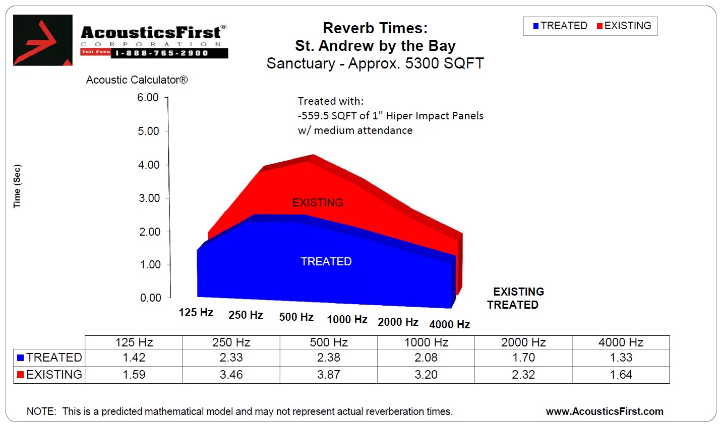
St. Andrew by the Bay is a traditional worship facility with a focus on spoken word worship and congregational singing. The large volume and hard surfaces in this space are the physical features most at fault for excessive reverberation, comb filtering and distracting “slap” echoes (discrete sound reflections usually caused by a distant, reflective back-wall).

To correct the slap-back and curb excessive reverb without “over deadening” the space, we recommend distributing approx. 550 SQFT 1” HiPer® Impact absorber/diffuser panels throughout the rear wall areas (see attached layout). HiPer® Impact panels absorb low frequencies and diffuse high-frequencies, yielding a much more even room response. In addition to controlling bass buildup, the high-frequency scattering will help retain some “life” in the room for acoustic and choral performances.
Reverb Prediction – Historically, churches relied on an abundance of hard surfaces to propagate sound to the rear of the nave, so they benefited from very long reverb times (upwards of 4-5s). Modern sound systems allow for a much more focused sound and equitable listening environment , so these extreme reverb tails are no longer necessary and can actually degrade the experience of the congregation. Churches of this size with a sound system and traditional worship services should have a reverb time somewhere in the 1.5-2.25s range. We entered the sanctuary’s dimensions and construction materials into our acoustic calculator and made a prediction of reverb times before and after treatment.
From Lee Hartman & Sons who performed the install “Here are some photos of the finished panels at St. Andrew by the Bay. It turned out great and client is very happy. Many thanks to Cameron for the detailed layout.”

Demystifying Acoustic Data: Part 2 – Test Material Mounting
Posted by Acoustics First in Absorption, Home Entertainment, Home Theater, Products, Recording Facilities, Theater on October 13, 2016
For anyone new to the world of acoustics, there is a multitude of terms, coefficients and numbers that are thrown around. This flood of information can seem intimidating, especially to beginners. In this series, acoustician Cameron Girard of Acoustics First® hopes to help you distinguish between what’s useful and what’s not.
Part 2: How Mounting in Testing Affects Sound Absorption Data
As I discussed in my previous article, the best way to compare the performance of sound absorbing panels is by referencing the Sound Absorption Coefficient (SAC) and Noise Reduction Coefficient (NRC). However, these coefficients are often used as marketing tools. Be on the lookout for companies that list absorption coefficients and NRCs without mention of a particular testing standard or mounting method. It’s vital to check for this information, as direct comparisons to competitors and other materials can only be made if their testing procedures are the same.
The sound absorption of a material that covers a flat surface not only depends on the physical qualities of the material but also on how the material is mounted during installation. The mountings specified in laboratory tests are intended to simulate conditions that exist in normal use, such as direct wall mounting and installation into a ceiling grid.

Many materials for treatment of walls or ceiling are tested using what is called Type ”A” mounting. Type ”A” mounting means the test specimen was placed directly on the test surface of the reverberation chamber. Lay-in ceiling tiles, on the other hand, are often tested using ”E400” mounting. The ”E” designates a sealed air space behind the specimen (simulating the air gap between a dropped tile ceiling and the structural ceiling) and the number after the ”E” is the depth of the airspace in millimeters. The airspace behind the acoustic material affects the sound absorption by acting as a bass trap. The deeper the cavity behind the panels is, the lower the fundamental of the “trapped” frequencies will be.

To see what this look like in terms of actual numbers, let’s take a look at how different mounting methods effect the sound absorption coefficients of Acoustics First’s HiPer® Panel (a low-profile, composite absorber/diffuser panel).
Since the HiPer® Panel can be used effectively in multiple applications; we had it tested in accordance to the two most-common mounting procedures, Type E-400 and Type A. The results of the laboratory tests are as follows:
|
Product Info |
Sound Absorption Coefficients |
||||||||
| Product Name | Thickness | Mounting | 125Hz | 250Hz | 500Hz | 1kHz | 2kHz | 4kHz |
NRC |
| 1″ HiPer® Panel | 1″ | E-400 | 0.43 | 0.28 | 0.51 | 0.76 | 0.99 | 1.10 | 0.65 |
| 1″ HiPer® Panel | 1″ | A | 0.09 | 0.28 | 0.78 | 0.75 | 0.94 | 0.85 | 0.70 |
As you can see from the chart, the sound absorption coefficient at 125 Hz varies greatly between E-400 mounting (SAC of .43) and Type-A mounting (SAC of .09). If mounting the HiPer® Panel in a ceiling grid, with a sizable airspace, you can expect significant low-frequency absorption, but mounting it on a wall (Type-A) will result in much less absorption at 125Hz.
Other mounting methods are available, but are not used as frequently. Here are some of the basic mounting designations (See ASTM E795 for more information.)
Type A mounting – Test specimen laid directly against the test surface (wall panel on drywall).
Type B mounting – Test specimen cemented directly against the test surface. Type B mounting is intended to simulate acoustical ceiling tiles or other sound-absorptive products adhered to a hard surface with an adhesive.
Type C Mounting—Test specimen comprising sound-absorptive material behind a perforated, expanded, open facing or other porous material.
Type D Mounting—Test specimen mounted on wood furring strips.
Type E Mounting—Test specimen mounted with an air space behind it (dropped tile ceiling).
As we’ve discussed, acoustical data can vary greatly depending on the mounting method used during testing. Acoustics First tries to include as much information about testing procedures as possible, because we feel an informed client makes the best client.
Contact Acoustics First for your all your sound control needs!
DIY Wood Diffusion Panel – ArtDiffusor® Trim
Posted by Acoustics First in Diffusion, DIY, HOW TO, Products on April 13, 2016

DIY Wood Diffuser Panel – Using ArtDiffusor Trim
Here at Acoustics First®, we are often asked about wood acoustic treatment for spaces ranging from recording studios and auditoriums to churches and home theaters. Although the acoustic properties of wood are comparable to other reflective materials like gypsum and thermoplastic, wood’s superior aesthetic makes it a desirable treatment (wood is often perceived to “sound better” simply because of its visual properties).

Two different profiles that work together!
Our newest wood acoustic treatment, ArtDiffusor® Trim, is a versatile, high frequency quadratic diffuser that can help improve the clarity of speech and music. Both Profiles (Type A & B) offer diffusion in similar ranges and allow for customizable installations. The different profiles can be used individually or together to modify the aesthetics of a room, while achieving the desired acoustic performance. In fact, in recent tests of ArtDiffusor® Trim, alternating the A and B profiles resulted in the best diffusion. Some examples of different installations include:
- Back wall Diffusion for a theater, listening or mixing studio.
- Slatted Ceiling Absorber.
- Installation over or behind stretch wall
- Chair rail, door and window molding.
ArtDiffusor® Trim can come in lengths up to 8’ and is available in Maple (other woods can be quoted). Later in this article we’ll walk you through how to build your very own diffusion panel using 4’ lengths of ArtDiffusor® Trim.
Diffusion at a Glance
Where typical fiberglass and foam panels absorb sound by transferring sonic energy into kinetic and thermal energy, diffusers act to scatter the energy, creating ambiance and a sense of open space. The function of sound diffusers is not to remove energy from your room, but to redistribute it, accurately reinforcing the sound source by controlling standing waves and flutter echoes, while retaining the room’s “liveliness”.
As is the case with any sound absorbing panels and diffusers, the treatment needs to cover enough critical surface area to make a noticeable impact. Simply installing a single piece of ArtDiffusor® Trim will not significantly improve the acoustics of a room. One way to ensure enough improvement is by using ArtDiffusor® Trim to build a series of diffusion panels and installing them as you would sound absorbing panels.
Building a Diffusion Panel – A step by step guide
- Plan out your Panel: Find out how many ArtDiffusor® Trim boards you want in your panel assembly. Our diffusion panel was to occupy an alcove that was 29” wide and each board has a width of just about 4”, so we opted for 7, 4’ boards. Remember, alternate type A and B profiles for optimal diffusion.

Plan your Layout.
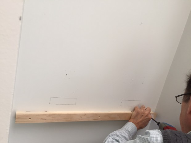
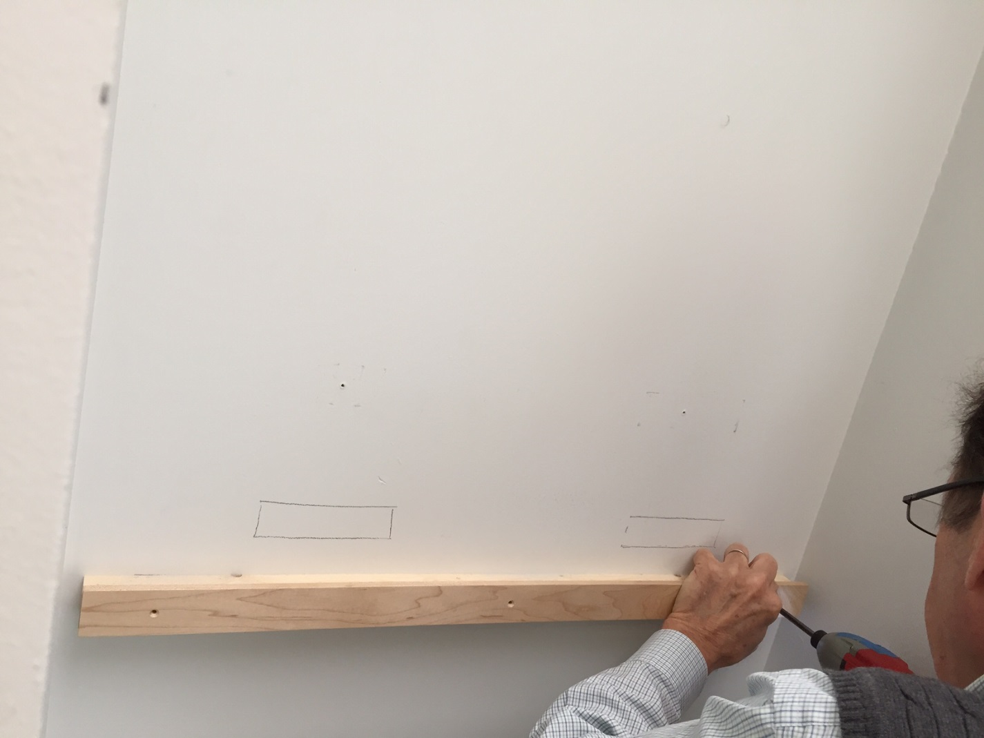
- Install the lower support board: This is what the ArtDiffusor® Trim boards will “stand” on. It is best to install acoustic treatment above chair rail height (3’-4’), to ensure that it’s effective around ear height. Measure and use a level to mark where the support board will go, install drywall anchors for a sure hold into the drywall, then drill and screw the support board into place. Be sure to countersink the holes so the facing strip has a flat surface to rest against.

Install the Lower Support.

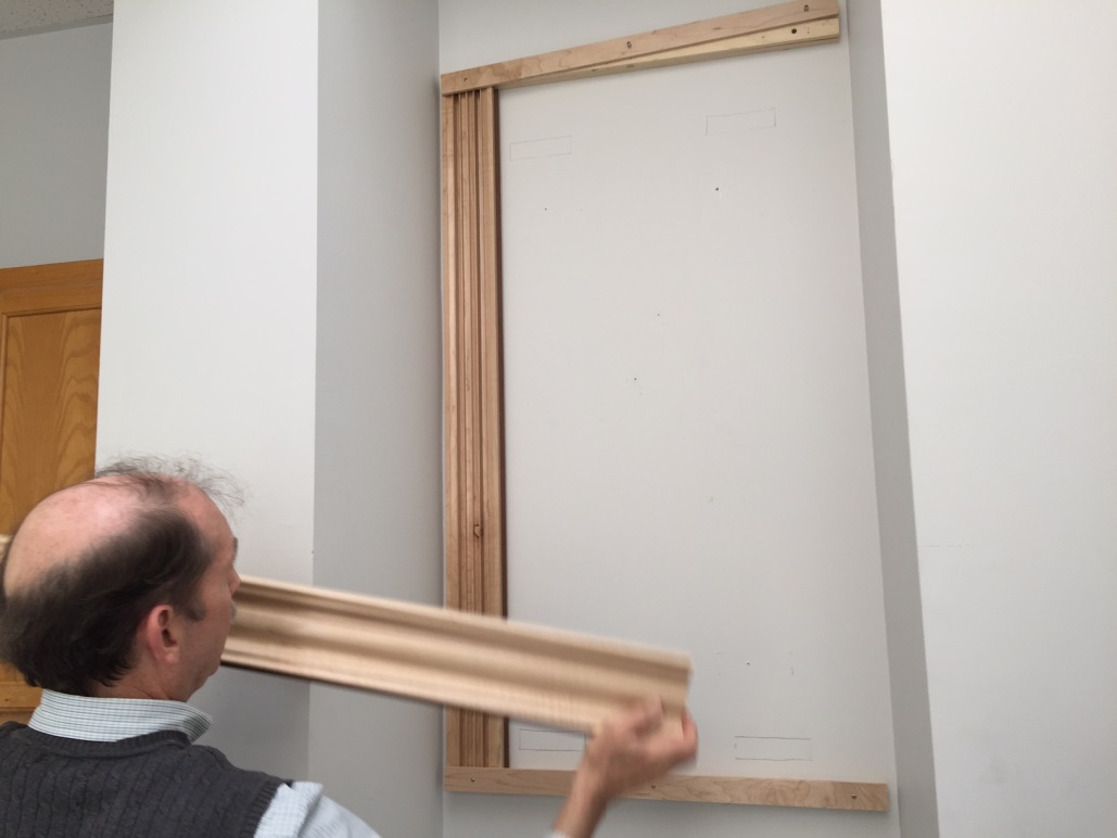
Install the upper support board: This time using the ArtDiffusor ® Trim boards as a guide, measure, level and mark the location of the upper support board. Again, using drywall anchors, mount the upper support board (don’t forget to countersink!).The picture shows both support boards installed.
———————————————————————————————–>>>- Attach lower facing strip: Use facing strip that is approximately a ½” wider than the support board. Line up the facing strip next to the support board and mark your screw locations ensuring that they won’t run into the support board screws. Drill the holes and counter sink, lining up the boards so the ½” overlaps on the top, and screw into place.
Lower facing strip installed.
- Partially attach upper facing strip: Same as the lower facing strip, but mount so the ½” overlap is on the bottom, and only screw one side in so it’s easier to slide in the ArtDiffusor ® Trim boards later.

Partially attach top facing strip.
- Slide in Art Trim: Slide in the ArtDiffusor® Trim behind the facing strip and use biscuits to fit the boards together. We decided to position the boards with an approximately 1/8” spacing.

Slide in ArtDiffusor® Trim panels.
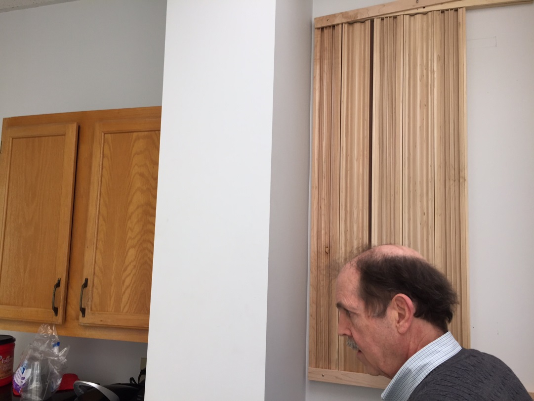
- Finish attaching upper facing strip & admire your new DIY Diffusion Panel!
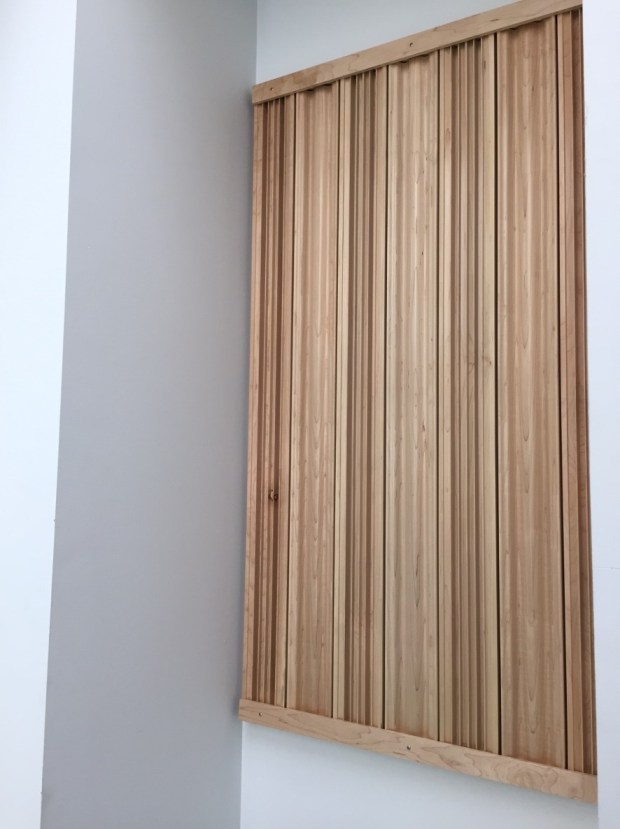
Final DIY Diffusing Wall Panel with ArtDiffusor® Trim!


You must be logged in to post a comment.