Everything you wanted to know about anechoic chambers… but were afraid to ask.
An anechoic chamber is a specialized room engineered to eliminate sound reflections. Its walls, ceiling, and—in the case of a full anechoic chamber—the floor are covered with wedge-shaped foam or fiberglass absorbers that prevent sound waves from reflecting back into the test space. This creates a highly controlled acoustic environment that approximates free-field conditions, allowing the sound source to behave as though it were suspended in open air with no nearby reflective surfaces.
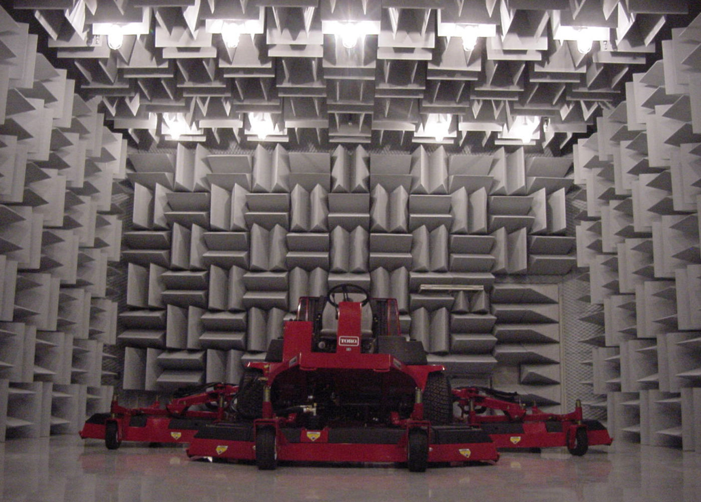
Such an environment is essential because acoustic measurements—including sound power, directivity, and frequency response—must be performed under known, reflection-free conditions to ensure repeatable, standards-compliant results. In the absence of these conditions, room reflections influence the measurements, causing the results to depend on the characteristics of the test room rather than the performance of the product being evaluated.
Here is a list of common measurement standards and the chamber/test requirements for each.
Precision Sound Power Measurement (ISO 3745)
ISO 3745 is the reference standard for precision sound power determination. It requires testing to be conducted in either a full anechoic or hemi-anechoic chamber that has been qualified to satisfy stringent free-field deviation requirements over the frequency range of interest. Chamber qualification requires demonstrating that the inverse-square law is maintained within ±1 dB at all specified measurement locations.
The typical chamber cut-off frequency ranges from 80 to 200 Hz, depending on the chamber dimensions and the depth of the acoustic wedges. Below the cut-off frequency, the chamber no longer provides true free-field behavior.
Engineering Sound Power Measurement (ISO 3744)
ISO 3744 establishes engineering-grade methods for sound power determination. While less stringent than ISO 3745, it still requires testing to be performed in a hemi-anechoic environment. The standard permits the application of environmental correction factors when the test environment does not achieve ideal anechoic performance, making it well suited for production-floor test cells and other facilities that approximate, but do not fully satisfy, free-field conditions.
Qualification of Free-Field Environments (ISO 2610)
ISO 26101 specifies the procedures for verifying that a test environment satisfies free-field performance requirements. It is the standard used to qualify an anechoic or hemi-anechoic chamber by confirming that the chamber’s acoustic characteristics meet the required free-field criteria and deliver the level of performance claimed for the facility.
Other Standards
- ECMA-74: IT equipment noise measurement (uses ISO 3745 or ISO 3744 as the underlying acoustic method)
- ANSI S12.55 / S12.56: North American equivalents of ISO 3744/3745
- ISO 11201-11205: Various sound pressure level determination methods, some requiring free field conditions
Chamber Size and Absorber Performance
The physical dimensions of an anechoic chamber determine its lowest usable frequency. As a general guideline, the chamber must be sufficiently large so that the distance between the sound source and each measurement microphone is at least one wavelength at the lowest frequency of interest.
For a chamber with a 100 Hz cut-off frequency, the minimum source-to-microphone distance is approximately 3.4 meters. Consequently, the internal chamber dimensions (excluding the absorber wedges) should be approximately 7–8 meters on each side for a hemi-anechoic chamber.
The depth of the acoustic absorber wedges governs the chamber’s low-frequency performance. Increasing wedge depth improves absorption at lower frequencies.
| Wedge Depth | Approximate Low-Frequency Cut-off |
| 200 mm | ~500 Hz |
| 500 mm | ~200 Hz |
| 1000 mm | ~80–100 Hz |
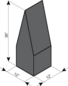
Common absorber materials include melamine foam (https://www.acousticsfirst.com/acoustical-foam-anechoic-chamber-wedges.htm , which is lightweight and inherently fire-retardant, and fiberglass, which provides superior low-frequency absorption but has a greater mass and higher cost.
Chamber Ambient Noise Floor
In addition to controlling sound reflections, an anechoic chamber must provide effective isolation from external noise sources. The ambient noise level within the chamber, measured with no test source operating, should be at least 6 dB—and preferably 15 dB—below the sound pressure level produced by the test object at the specified measurement positions.
Achieving these background noise levels typically requires a chamber constructed with multiple layers of high-mass materials, such as concrete and steel, combined with vibration-isolated mounting systems to minimize the transmission of structure-borne noise.
Alternatives to an Anechoic Chamber
Not every organization can justify the investment required for a purpose-built anechoic chamber, which typically ranges from $500,000 to more than $2 million. Fortunately, several practical alternatives are available, depending on the measurement objectives and required level of accuracy.
Sound Intensity Method (ISO 9614)
The sound intensity method, defined in ISO 9614, is inherently less sensitive to room reflections because sound intensity is a vector quantity. Unlike sound pressure, it differentiates between outgoing acoustic energy radiated by the test source and incoming energy reflected from surrounding surfaces. As a result, sound power can be determined in ordinary rooms without the need for anechoic treatment.
The primary trade-off is that this method requires specialized sound intensity probes and more complex measurement procedures than conventional sound pressure measurements.
Acoustic Test Boxes
For small products, such as electronic devices, individual components, and transducers, a desktop acoustic test box provides a controlled, low-noise environment that approximates anechoic conditions over a defined frequency range. These systems offer a significantly lower-cost alternative to a full-sized anechoic chamber and can be integrated directly into production-line testing.
Portable Acoustic Arrays
Modern acoustic imaging systems, commonly referred to as acoustic cameras, use portable microphone arrays to identify and localize noise sources in situ, whether on the factory floor, along a production line, or in field applications, without requiring an anechoic environment. Although these systems are not a substitute for standards-compliant sound power measurements, they provide a rapid and effective means of diagnosing and visualizing noise sources that would previously have required dedicated chamber testing.
Contact Acoustics First about your acoustic chamber project to find what sort of treatment is best suited for your application!


You must be logged in to post a comment.